
#1 - Your Raspberry Pi
This is where we'll start, with the brain of the circuit. The Raspberry pi will connect to all of the components we'll be using, controlling LED's and reading Buttons and Temperature Sensors.

#2 - Add a BreadBoard
The BreadBoard will allow us to connect all of the components together, making a circuit.

#3 - Add a Red LED
Connect a Red LED to the two far left adjacent pins as shown.
Insert the shortest leg to the outside of the board.

#4 - Connect Red LED Ground
Add a Purple Wire from the Red LED short Leg to Pin 9 (Ground / 0v)
This is one side of the circuit to light the Red LED

#5 - Add a 220Ω Resistor
Connect a resistor between the Red LED Long Leg hole and the adjacent hole.
This limits the current to the LED, preventing the Pi Pin from burning out.

#6 - Connect Red LED Control
Connect an Orange Wire to the hole on the empty side of the Red LED Resistor to Pin 10 (Wiring Pi Pin 16).
This is the control to turn our Red LED On and Off.

#7 - Add Green LED
Insert the Green LED with it’s shortest leg to the outside of the breadboard.
It’s the same column as the Red LED.
Insert it’s longest leg into the hole next to the Red LED Resistor.

#8 - Add another 220Ω Resistor
Connect a resistor between the Green LED Long Leg hole and the adjacent hole.
This limits the current to the LED, preventing the Pi Pin from burning out.

#9 - Connect Green LED Control
Connect a Grey Wire to the hole on the empty side of the Green LED Resistor to Pin 11 (Wiring Pi Pin 0).
This is the Control to turn our Green LED On and Off.

#10 - Add a Button
Connect the Button between the two sides of the Breadboard.
It will only fit in one orientation!
Don’t force it!
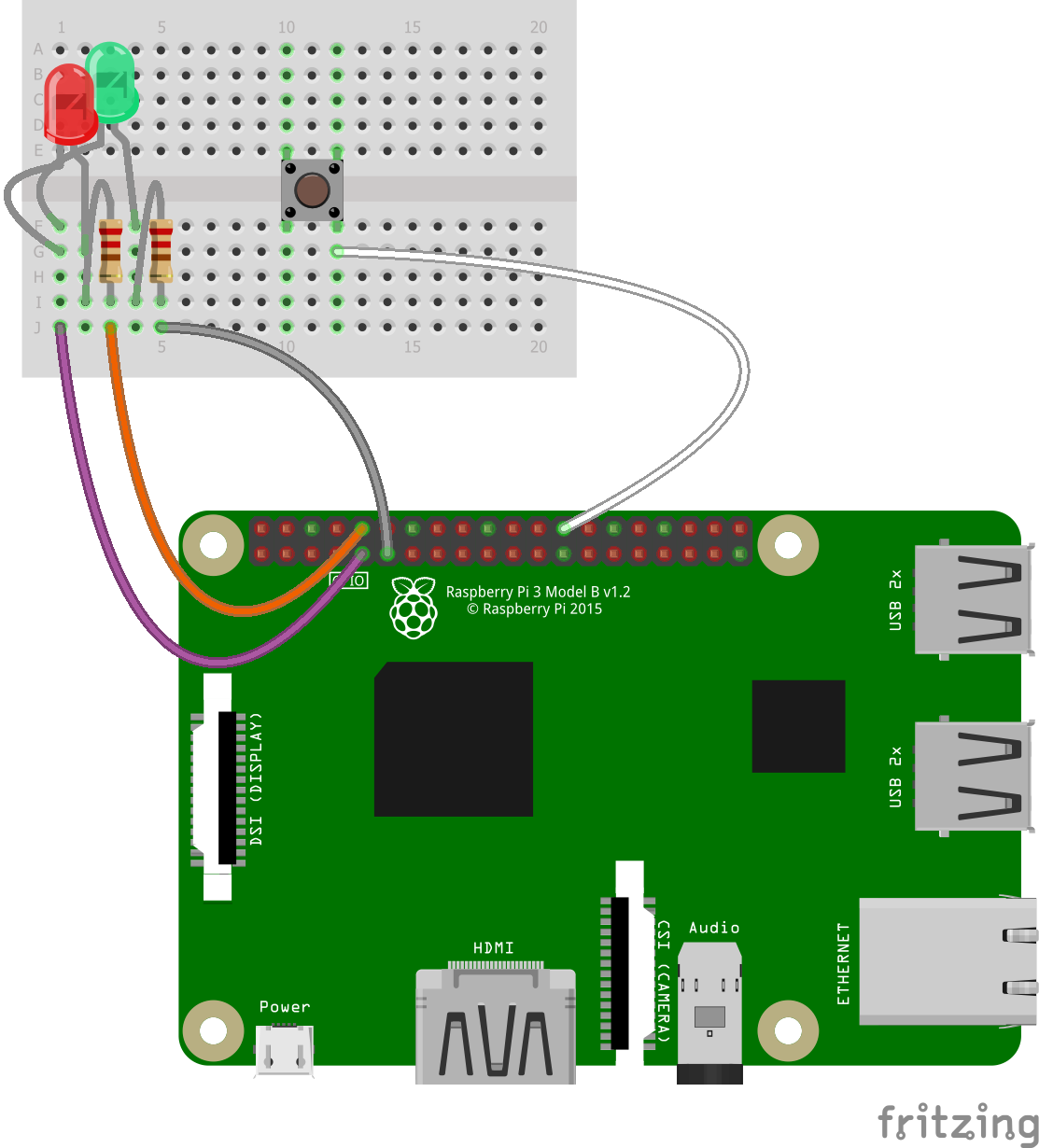
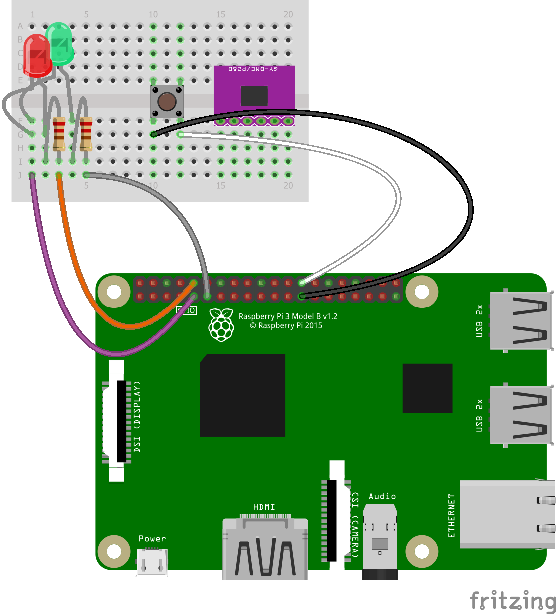
#11 - Add Button Control
Connect a White Wire from the Right Hand Button Leg Hole to Pin 26 (Wiring Pi Pin 11).
This is one side of our Button Circuit, and how we’re going to sense if the Button has been pressed.
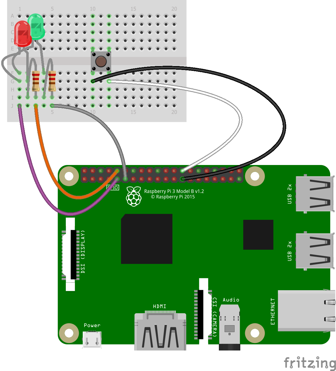
#12 - Add Button Ground
Connect a Black wire from the Left Hand Button Leg Hole to Pin 25 (Ground / 0v).
This is the other side of our Button Circuit.
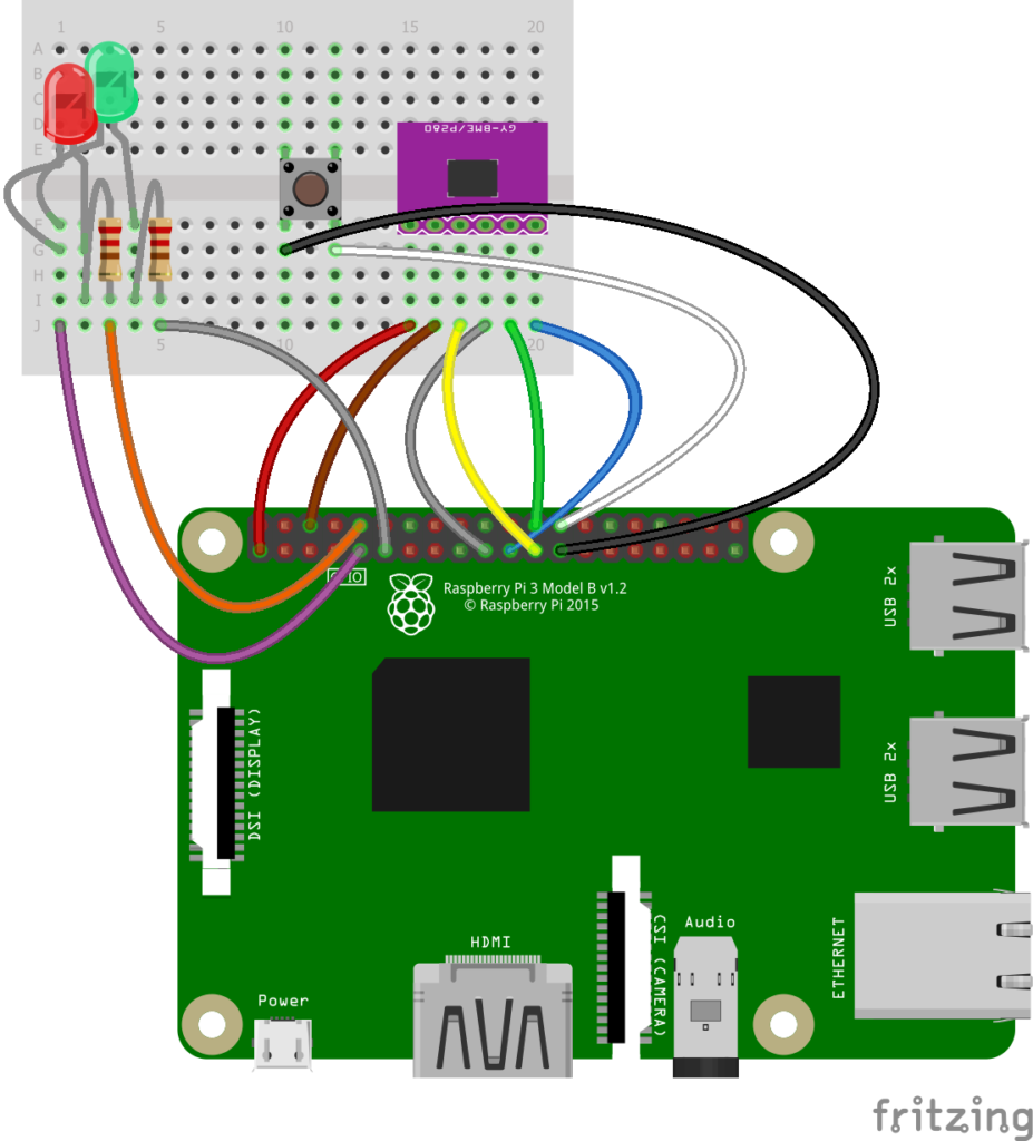
#13 - Add the BME280
This is our Temperature / Humidity / Pressure Sensor.
Insert the BME with the body overlapping the gap, and the pins in the bottom half of the breadboard.

#14 - Add BME280 Power
Connect a Red Wire from the left most BME280 Pin Hole to Pin 1 (3v).
This supplies the power for the Sensor.

#15 - Add BME280 Ground
Connect a Brown Wire from the Pin Hole to the right of the Red Wire to Pin 6 (Ground / 0V).
This is our 0v and part of the power to the BME280.
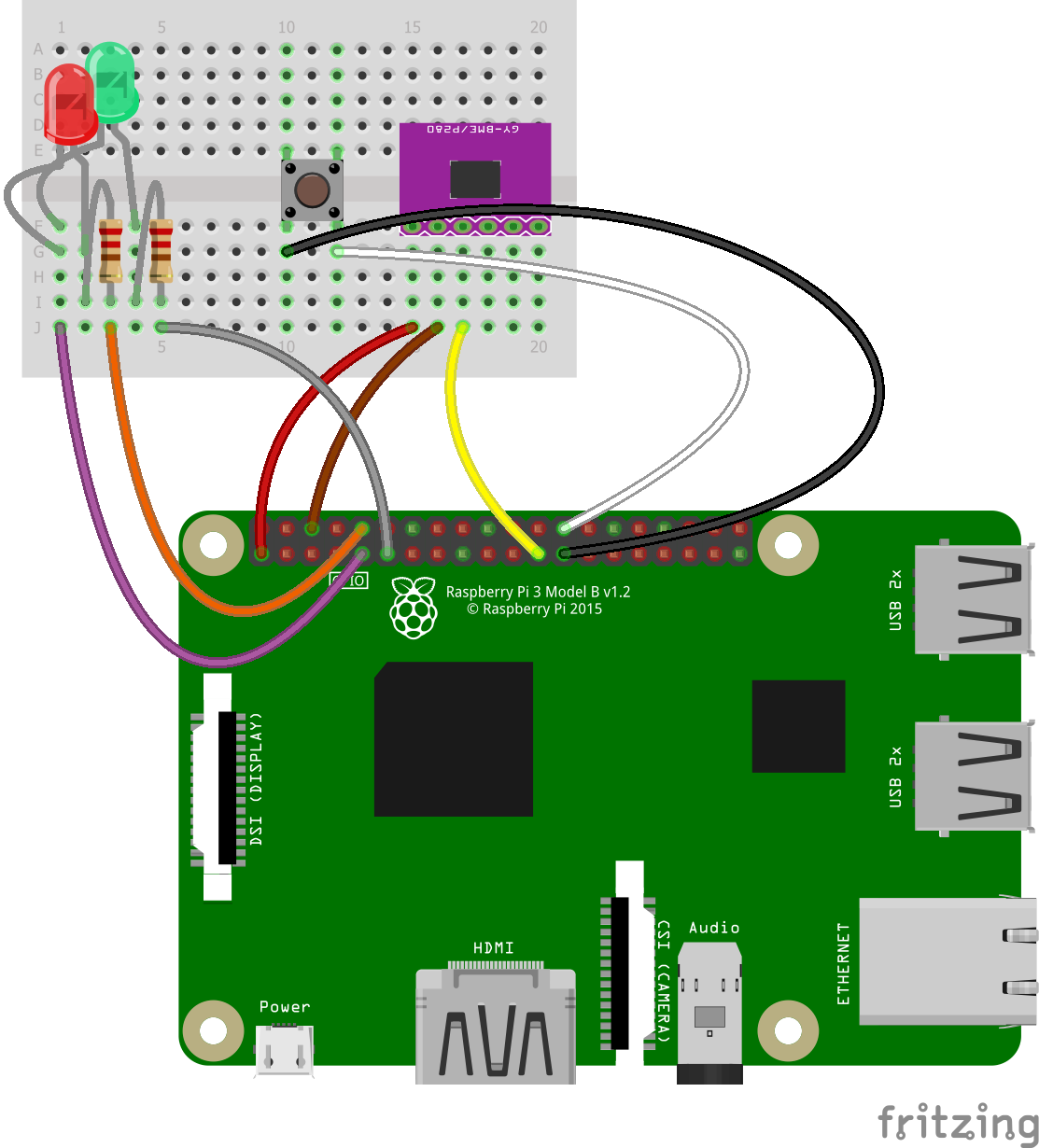
#16 - Add BME280 Clock
Connect a Yellow Wire from the Pin Hole to the right of the Brown Wire to Pin 23 (Wiring Pin 14 / SCLK).
This is the clock for the SPI (Serial Peripheral Interface).
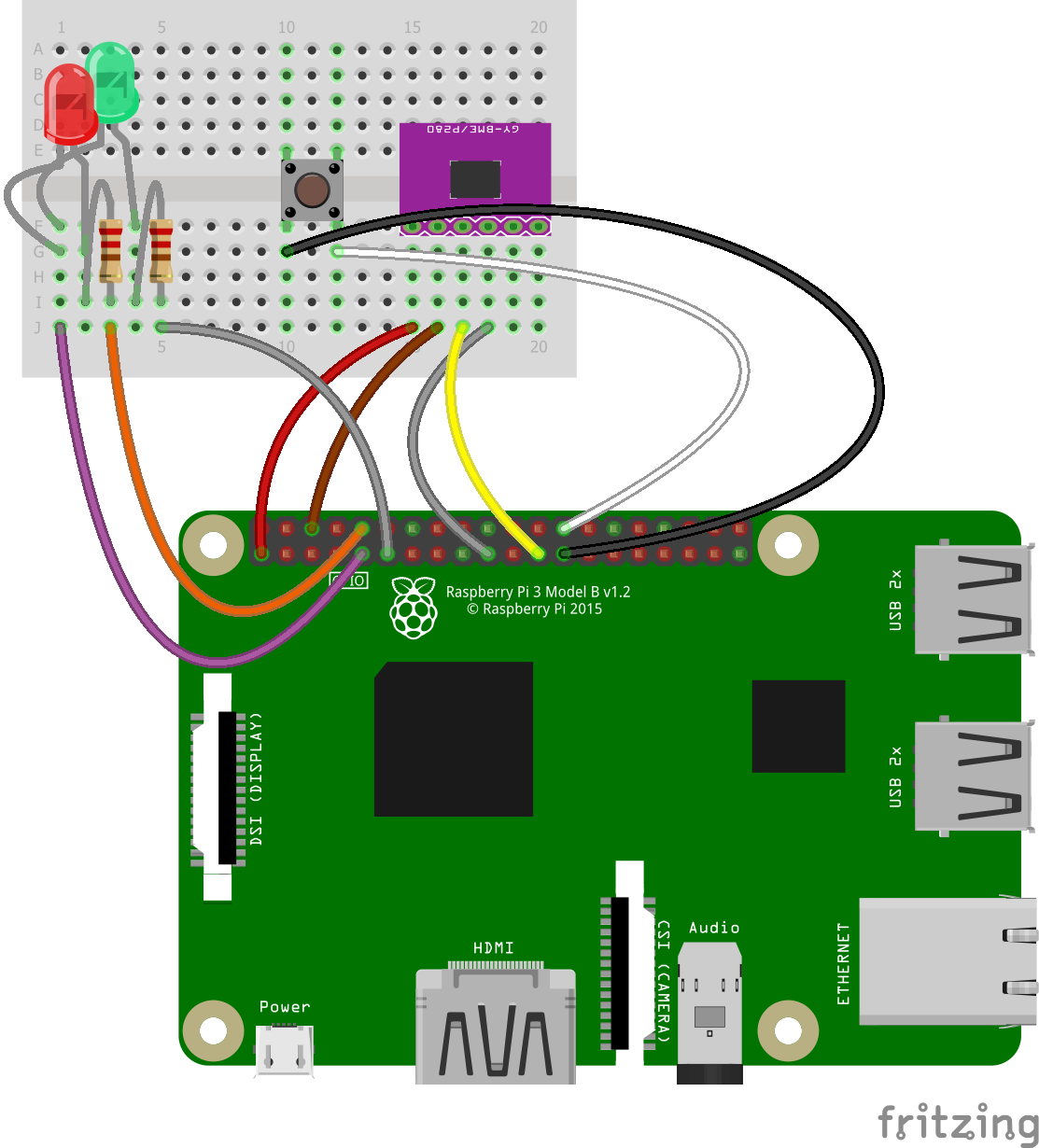
#17 - Add BME280 Serial In
Connect a Grey Wire from the Pin Hole to the right of the Yellow Wire to Pin 19 (Wiring Pi Pin 12 / MOSI).
This is the Serial Data from the BME280 to the Raspberry Pi.

#18 - Add BME Chip Enable
Connect a Green Wire from the Pin Hole to the right of the Grey Wire to Pin 24 (Wiring Pi Pin 10 / CE0).
This allows the Raspberry Pi to Enable the BME280 in case there are multiple SPI devices connected.

#19 - Add BME280 Serial Out
Connect a Blue Wire from the far right Pin Hole to the right of the Yellow Wire to Pin 21 (Wiring Pi Pin 13 / MISO).
This is the Serial Data from the Raspberry Pi to the BME280.